Repairers' notes
Findings contributed by people repairing sets: pin mappings, fitting differences, parts that can stand in for one another. They are not HR Diemen data, and each says how sure it is. 3 so far.
B&O MX 4000 / MX 7000 fitment, and where to look for one (Orega 40308-17)
A repairer reports this part in a B&O MX 4000 in France, added as a contributed fitment. HR lists it for "MX 700O", read here as MX 7000 and also added. The MX 4000 (from 1992) shares its chassis with the MX 6000 and MX 7000. Despite the similar names it is unrelated to the earlier MX 4500/5000 (1988-91, Orega 40317, HR 7321): different pin-out (B+ 11, collector 3), split-diode EHT, 27.3 kV. Scarce: Wiltsgrove's LT-918P was out of stock in October 2026. See the inferred sibling HR 6680. Source
B&O MX4500 / MX5000 flyback footprint and pin mapping (Orega 40317-21)
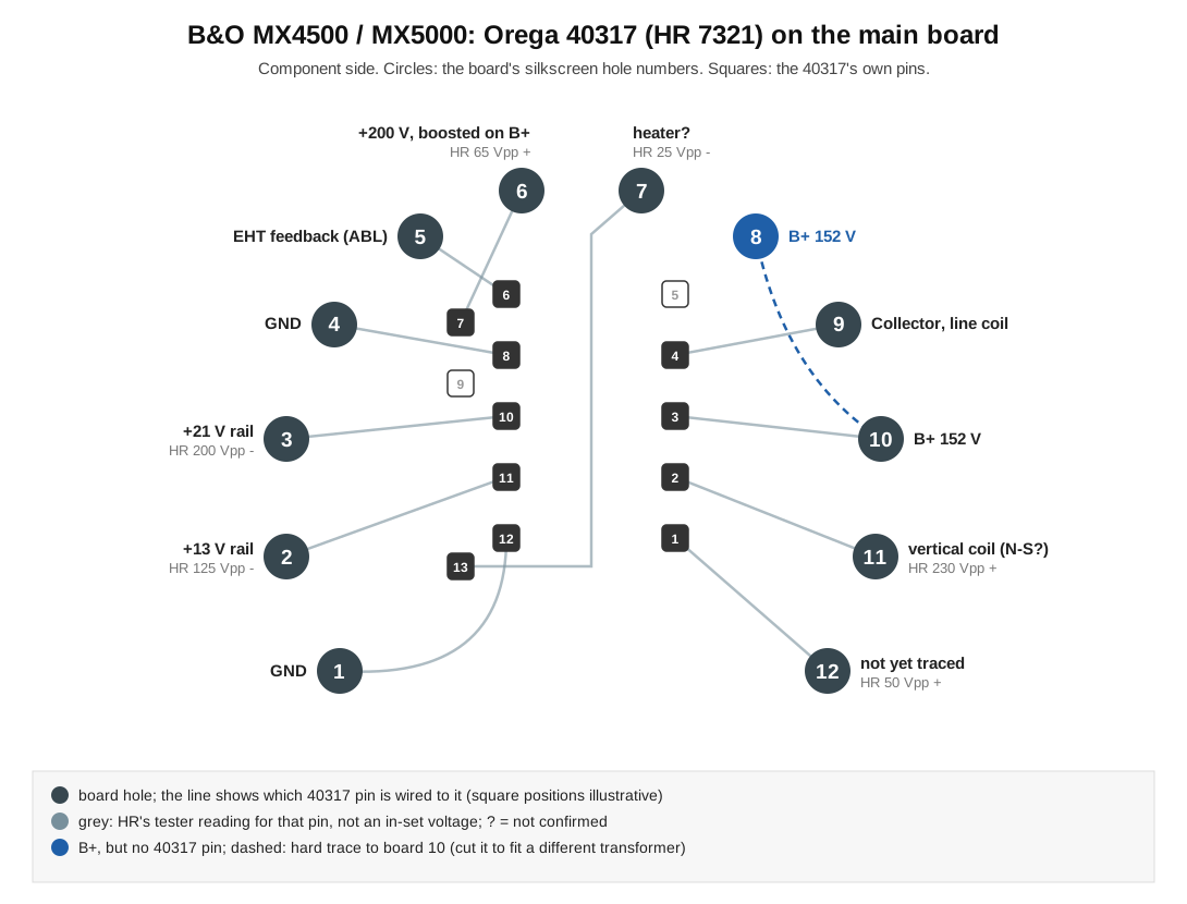
Traced on a B&O MX5000 main board fitted with an Orega 40317-21 (two straight rows of pins, as on this sheet). The board also has a 12-hole horseshoe footprint, numbered 1-12 on the silkscreen, and the 40317's pins are wired into those holes. Pin numbers in the B&O service manual are those board holes, not the transformer's pins: for the fitted 40317, board holes 1-12 are its pins 12, 11, 10, 8, 6, 7, 13, (none: hole 8 is B+ too, hard-traced to board 10), 4, 3, 2, 1, so the manual's B+ (board 10) is pin 3 on the part. In the MX5000 (B+ 152 V), per the service manual and board: board 2 and 3 give +13 V and +21 V rails (trace-rectified, roughly HR's Vpp divided by 9); board 5 is EHT feedback to the ABL circuit; board 6 gives +200 V, peak-rectified onto a capacitor stacked on B+; board 9 is the collector and line coil; board 11 feeds the vertical coil through a tuned network, probably North-South correction. HR's sheet for this part is drawn from the pin side: the offset 7/13 sub-row on the real part only matches it seen from below. The horseshoe holes follow the common Orega horseshoe layout; what B&O meant to fit there is not known. Separately, the 2003 database lists B&O 80140897 beside 8014097: B&O flyback numbers run 8014xxx, so the eight-digit one is almost certainly a typo.
Orega 40315 in the B&O MX4500 / MX5000 horseshoe footprint (inferred)
Repairer's inference, not a known fitment: this part's pin layout fits the spare horseshoe footprint on B&O MX4500/MX5000 main boards (traced on an MX5000, which is fitted with an Orega 40317, HR 7321). There is no evidence B&O ever fitted a 40315 there. The B&O silkscreen counts the horseshoe the other way round to HR, so this part's pin p would sit in board hole 13 - p. Most functions line up (secondary taps within about 10% of the 40317's; the aux tap is about 25% low), but only as a last resort for a dead set, and three things must be dealt with first. (1) Holes 8 and 10 are both B+, joined by a hard trace: this part's B+ (pin 5) lands in 8, but its pin 3 carries a primary tap and lands in 10, so the trace must be cut. (2) Pin 6 (board 7) gives a positive 25 Vpp pulse where the board expects a negative one. (3) This part is rated 30.9 kV against 20.7 kV on the HR 7321 sheet.
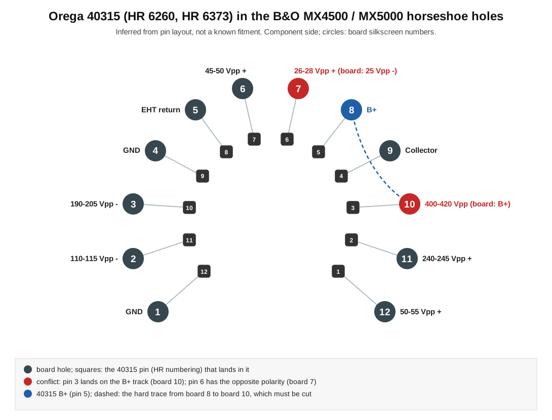
Repairer's inference, not a known fitment: this part's pin layout fits the spare horseshoe footprint on B&O MX4500/MX5000 main boards (traced on an MX5000, which is fitted with an Orega 40317, HR 7321). There is no evidence B&O ever fitted a 40315 there. The B&O silkscreen counts the horseshoe the other way round to HR, so this part's pin p would sit in board hole 13 - p. Most functions line up (secondary taps within about 10% of the 40317's; the aux tap is about 30% low), but only as a last resort for a dead set, and three things must be dealt with first. (1) Holes 8 and 10 are both B+, joined by a hard trace: this part's B+ (pin 5) lands in 8, but its pin 3 carries a primary tap and lands in 10, so the trace must be cut. (2) Pin 6 (board 7) gives a positive 25 Vpp pulse where the board expects a negative one. (3) This part is rated 27.9 kV against 20.7 kV on the HR 7321 sheet.
Have something to add? See CONTRIBUTING.md in the repository.